Forum Replies Created
-
AuthorPosts
-
pidtuner
KeymasterIf you are experiencing oscillations, either your control action is too aggressive or your system has to much phase lag. Both conditions are equivalent, if your system has too much phase lag (delay), you are restricted on how aggressive the control can be. Another cause could be hat you are not sampling fast enough.
Without more details about your system it is hard to diagnose this. If both systems are exactly equal in terms of, sampling time, control algorithm, etc. Most likely the issue is hardware, maybe one of your drives is experiencing more friction, which has similar effects as phase lag.
If you want more help, you need to share as much data as possible, one screenshot is not going to cut it I am afraid.
KeymasterHi,
Thanks for notifying the Error code. That needs fixing indeed.
Regarding the difference between simulations, maybe this other question is the cause:
Basically, the PID implementation applied the D gain on the measurement, not on the error.KeymasterHi, thanks for the kind comments.
Sadly I stopped working on control engineering software due to low or no wages. Now I develop cloud software where grass is greener. I came to realize that the closer the job is to the money, the better the living conditions.
It is a shame that control is always assumed to just “be there” when a product or a project is sold. Control engineering is, as seen by the people that pay, just one small part of something else. Thus nobody appreciates its value.
On the contrary, when working on software when the software itself is the product (cloud, mobile apps, etc), then people are willing to pay for it.
Having said that, if I even come to a position where I am financially independent, at a point in which I can choose where I spend my time on, then I would definitively spend my time developing more advanced control, since it is something I am still passionate about.
Cheers!
KeymasterI am afraid that the final PID closed loop simulation on the web tool cannot be easily adjusted to add limits on the simulated PID.
You can take the identified model parameters from the PIDTuner and use them to create a custom simulation on Python or Matlab.
The same goes for the tuning provided by the tool, it gives some initial tuning with a simple slider for adjustment, if you wish to fix the overshoot, you have to de-tune the gains (slider to the left) until no overshoot is seen, or set your own PID tuning rules in an external Python or Matlab simulation environment.KeymasterIt is likely that you are passing the wrong values, you need to pass exactly what comes in and what comes out of the PID block. Refer to this guide for more details:
https://github.com/pidtuner/pidtuner.github.io/blob/master/assets/doc/PID%20Tuner.pdfKeymasterHi, thank you for your interest. Sadly we do not provide commercial services, but we do have some material that can guide you through a proper usage of the tool:
https://github.com/pidtuner/pidtuner.github.io/blob/master/assets/doc/PID%20Tuner.pdf
https://www.youtube.com/@pidtuner7405/videos
Hope this helps
KeymasterHere are a few tips:
https://github.com/pidtuner/pidtuner.github.io/blob/master/assets/doc/PID%20Tuner.pdf
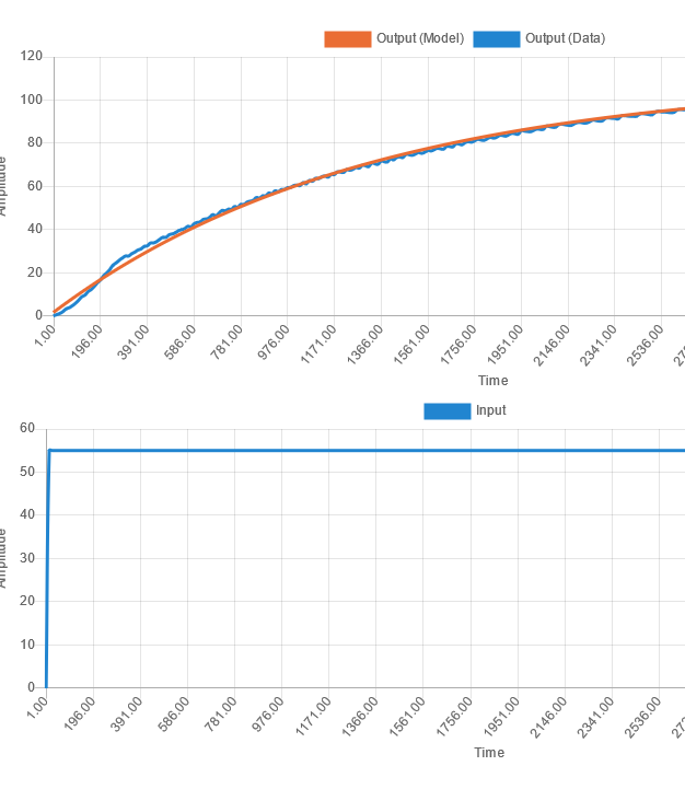
It all boils down to having good (noise and perturbation free) step response data.KeymasterYour data does not show any delay, the process is responding immediately to an input change.
If you want the tool to detect a dead-time, it must be able to see the dead time.
I.e. if your process had a dead-time, it would have a flat output during the dead-time after a change in the input.
 Keymaster
Regarding the gains, I show all 5 because some PID implementations use gains, other implementations use times. Just plug in the values that your PID implementation requires. Wikipedia is always your friend.
Maybe this helps:
https://en.wikipedia.org/wiki/PID_controller#Standard_versus_parallel_(ideal)_form
https://github.com/pidtuner/pidtuner.github.io/blob/master/assets/doc/PID%20Tuner.pdf
KeymasterHey, happy to hear it worked for you with ease.
As you can imagine, the algorithm is rather complex, but generally speaking, it consists of:- a series of both linear and nonlinear system identification techniques to identify the models based on your data.
- skogestad’s IMC rules for PID tuning based on the models (https://folk.ntnu.no/skoge/publications/2003/tuningPID/more/tuningpaper_reno-2001/tuningpaper_06nov01.pdf)
The PID tuning rules are just given as a tuning starting point. The valuable information are actually the models, you can use any tuning rules over the models to achieve whatever you want with your PID.
Cheers
KeymasterHi, have you had a look at the following guide? If so, is it still unclear?
https://github.com/pidtuner/pidtuner.github.io/blob/master/assets/doc/PID%20Tuner.pdfKeymasterThat is correct, the derivative part is:
PID_D = -(D/Ts) * (yk – ykm1);Just like in here
KeymasterHi, the PID algorithm for simulation is similar to this PID implementation:
KeymasterGlad to hear the PDF solved some of your questions.
Regarding the size of the increments, it should be large enough, such that the output signal can be clearly distinguishable from noise.
In other words, the size of the increments should be large enough such that the output signal displays a clear curve that the pidtuner tool can identify, but not too large so you avoid damaging your hardware.
As a rule of thumb, I always try to split my operating range in 3 to 5 levels.KeymasterHi, thank you for using pidtuner.
Looking at your test data, it seems that the step response test has not been done properly. Please look at the following guidelines to make a proper step response:
https://github.com/pidtuner/pidtuner.github.io/blob/master/assets/doc/PID%20Tuner.pdf
-
AuthorPosts