Forum Replies Created
-
AuthorPosts
-
February 4, 2021 at 11:08 am in reply to: Can I somehow limit the max. amplitude in “TUNE PID” section? #69
pidtuner
KeymasterHi,
I have been thinking of adding this option in the simulation. Will probably add it in the near future as soon as I have the time.
Regardless, as long as your PID implementation has anti-windup mechanism, the PID tuning given by the tool should give you a very good starting point in spite of the limits. Then you can just fine tune online to achieve the desired response.
Thanks for the feedback! Let me know if you have more questions.
KeymasterHi Jacob,
If you really want to understand how a PID is implemented, I highly recommend you to read the following blog series:
They are short and well explained, also is the implementation used in the pidtuner tool.
Regarding the PID parameters, some PID implementations use PID gains directly (so called parallel or ideal form), other use times (so called standard form). That is why the tool provides both, then the user must use the ones that their PID requires. Read:
https://en.wikipedia.org/wiki/PID_controller#Standard_versus_parallel_(ideal)_form
Hope this is helpful.
KeymasterHi,
Sorry for the delay. Was offline for holidays. I tried to load your project, but the data saved seems to be the demo data. Can you please load the data again to that project and save it again? Else you can post the data here directly.
Cheers.
KeymasterThen your test data is still incorrect, what you need is to do is:
- Wait until the process output has settled in one operating point
- Apply one single step in the process input.
- Wait until the process output settles again into another operating point.
The data you shared is not useful, because you make many small changes in the input and do not let the output settle. What we need is one single input step and record how the output settles from one stable value into another one caused by the input change.
KeymasterHi, Sadly your data is not correct, these are the issues:
- Your data is undersampled. You need to sample faster so the process output response dynamics due to a step change in the process input are clearly visible.
- Your output process curve does not seem to be correlated to your process output curve. I see no correlation between the input of the process and the output. Are you sure you have selected the correct variables in your data.
Take a look at the sample data provided by the tool, you can see a clear correlation between a step change in the input and a slow transitioning on the output to another level. This is what you should be able to see on your data.
Also make sure your PID is turned off during the experiment and that your process input is exactly what would get out of your PID and the process output is exactly what would get in to the PID.
KeymasterThen go and convert your time values to seconds. Then fill up the table in the pidtuner, placing the values on each corresponding column. Once the table is complete, verify the charts display the data as expected to confirm that you introduced the data correctly.
Then click the “Save” button and copy the link that the pidtuner shows you. Paste that link here and then I can help you move forward.
KeymasterIt should always be in seconds, and as time goes, it should always be increasing. To see an example, simply load the test data included in the tool. See the tutorials as well:
KeymasterAssuming you have setup your hardware correctly, the PID controller does not care about the details of all of it. To tune the PID controller, we just need a simplified “model” for everything that is outside of the PID controller. So for a moment, please forget about your hardware details, and think as if you were the PID controller and know nothing about what is outside.
We are the PID controller, and to know what gains to use, we will try to guess what it is that we need to control. So we will try to obtain that simplified “model” of the outside. The input of such “model” is the output of the PID controller, and the output of the “model” is what we feed as input to the PID controller. In your specific case the input of the “model” is the what gets out of the PID controller, so the TurnSpeed. The output of the “model” is what we are trying to regulate or steer, which your case is the GPSHeading.
I understand that you also use a “Setpoint” (what you call “Aim”) to form the error that is then fed to the PID controller, but we will forget about that “Aim” as well because the “Aim” does not get affected by a change of the TurnSpeed, only the GPSHeading is affected by the TurnSpeed, so the “Aim” is like an external disturbance and is not relevant for our model, because we are only interested in what we can actually control.
So we are the PID controller, how to we model everything that is outside us? Well, we do as any person would do. We make experiments and see what happens. Since the TurnSpeed is the only variable we can manipulate, me make a small change to it and see what happens. We go a little bit up and little bit down and we see how the GPSHeading responds, because that is the variable we want to regulate.
Control theory tells us that if we design that experiment to be a step change on the input (TurnSpeed), we get enough information to create a “model” that is good enough for control (good enough to make a good PID controller tuning).
And this is what the pidtuner tool helps you to do. It takes your step response experiment and makes a “model” of everything that is outside of the PID controller, and then uses that “model” to give you some PID gains that will be good enough to regulate that “model”.
So you give your data to the pidtuner in Step 1 of the tool, then on Step 2 you select a time range in your data where you can select where a step change in the input (TurnSpeed) occurs, so when your click next, the pidtuner can generate some models for you.
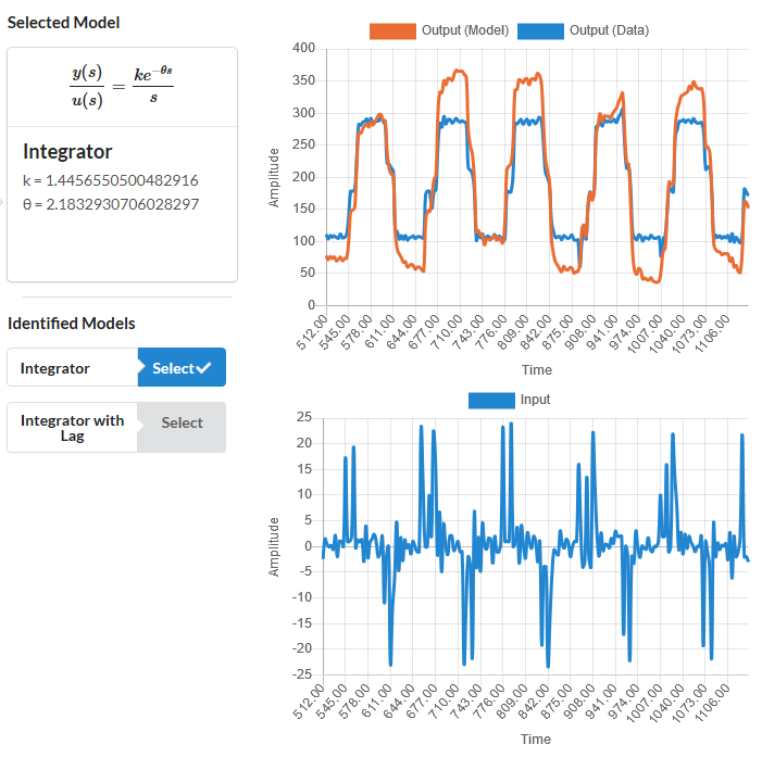
Notice that I said before; “to regulate that model”, meaning that the “model” has to resemble reality somehow, for the PID tuning to be successful. That is what you see in the Step 3 of the tool where it says “Select Model”. It compares the output generated by the models that the pidtuner has created for you, against the actual data of your experiment. Your job in that step is to select a model that resembles the actual data. The closest the model output looks like the data, the better. It does not has to be perfect though, there is some room for error in the gain, as long as the relevant dynamics are captured.
If no model resembles your data then you have to get back to any of the previous Steps. Either go back to Step 2 and select a different time range that contains better information about the step response. Or even go to Step 1 and import data from a better experiment. This is what I proposed to you, to make a better experiment by making manual steps in the TurnSpeed. If you want to see how a good experiment looks, take a look at the sample data that the pidtuner has by default. That data is actually from a drone pitch angle response.
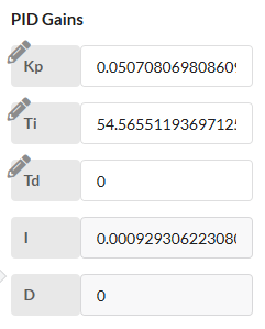
Once you have a good model-data match, you can get to Step 4 and get the PID gains that you need. In Step 4 you can simulate how the “model” would respond to a change on the “Setpoint” (for you is the “Aim”). You can use the “Scale Gains” slider to make the PID gains more or less aggressive. Then you can see how much time it would take for the model to reach the desired “Setpoint” (“Aim”). Beware that the more aggressive you tune the PID gains, the less robust it will be. That can be seen in the Bode Plot that is shown also in Step 4, but understanding robustness trade-off against performance and how it relates to the Bode Plot is too complicated to explain here and requires university level of engineering studies. You can get a grasp of it by watching some youtube videos though. If you are interested, checkout the youtube channel of Brian Douglas:
https://www.youtube.com/watch?v=ThoA4amCAX4
But you really don’t need all that advanced knowledge just to tune your PID, just follow the instructions I gave you for the tool and you should be good to go.
KeymasterHi,
The input to the pidtuner should be the “TurnSpeed” and the output should be the “GPS Heading”. I tried to import your data to the pidtuner using the “Loop Timer” as the time, but divided by 1000 to get the seconds.
Sadly your data does not contain clean manual steps on the input (TurnSpeed). These should be performed in open-loop (PID turned off). Some steps up and down while recording the output (GPD Heading).
Still the pidtuner gave somewhat of a match, see the following link:
https://pidtuner.com/#/0eDJOt49JM
I would try some conservative PID gains first like the ones shown in the link, then if it works, move the slider right to mak the PID gains gradually more agressive.
Still the bets thing to do would be to repeat the experiment, providing some clean steps on the “TurnSpeed”.
KeymasterHi,
I am guessing you mean how to obtain the input/output data required in the first step of the PID Tuner.
If that is the case, then you need to find where the PID code is executed (if is a PLC then find the PID block). Then record:
The output of the PID block is what the PID Tuner needs for the input column.
The input of the PID block (which is the process measurement) is what the PID Tuner needs for the output column.
The time of the experiment.
As you see input and output are inverted between the PID block and what the Tuner expects.Now to obtain the experiment data : With the PID block turned off, execute an experiment by making a manual step change on the PID output (what would be the Tuner input) and record all the data of that experiment. If you can make more steps, the better. Try steps up and down if possible. Then load that data into the PID Tuner.
Once you load that data, save your project and share your link here, so I can further assist you.
KeymasterHi,
I am guessing you mean how to obtain the input/output data required in the first step of the PID Tuner.
If that is the case, then you need to find where the PID code is executed (if is a PLC then find the PID block). Then record:
- The output of the PID block is what the PID Tuner needs for the input column.
- The input of the PID block (which is the process measurement) is what the PID Tuner needs for the output column.
- The time of the experiment.
As you see input and output are inverted between the PID block and what the Tuner expects.
Now to obtain the experiment data : With the PID block turned off, execute an experiment by making a manual step change on the PID output (what would be the Tuner input) and record all the data of that experiment. If you can make more steps, the better. Try steps up and down if possible. Then load that data into the PID Tuner.
Once you load that data, save your project and share your link here, so I can further assist you.
KeymasterHi,
First you need data from your flight system.
You need to turn off the PID and make a manual step change and record the data of the step change and the response of the flight system.
If you don’t know how to do this, checkout this tutorial:
Once you have that data, you can import it into the pidtuner tool. If you already have that data, share it here and we can help you.
-
AuthorPosts