PID Tuner Forum › Forums › General PID Discussion › Differential drive PID tuning
Tagged: PID tuning
- This topic has 11 replies, 2 voices, and was last updated 3 years, 11 months ago by
mdbirley.
-
AuthorPosts
-
August 17, 2020 at 8:22 pm #42
mdbirley
ParticipantHi
I would appreciate you help to undertake a useful test of your site. I have a RTK GPS differential drive robot that uses pure persuite controller to steer to a track between waypoints. It uses the error between the aimpoint and actual gps heading. We record lates longs and many other data values. We drive the robot by applying different wheel speeds to the drive wheels. We use a hardware controlled close loop PID to ensure the wheels drive at the correct speed.. We also measure the cross track error but we do not use this as yet in the actual controller. What specific data do we need for your simulator to worl
regards
August 18, 2020 at 12:40 pm #43pidtuner
KeymasterHi,
I am guessing you mean how to obtain the input/output data required in the first step of the PID Tuner.
If that is the case, then you need to find where the PID code is executed (if is a PLC then find the PID block). Then record:
The output of the PID block is what the PID Tuner needs for the input column.
The input of the PID block (which is the process measurement) is what the PID Tuner needs for the output column.
The time of the experiment.
As you see input and output are inverted between the PID block and what the Tuner expects.Now to obtain the experiment data : With the PID block turned off, execute an experiment by making a manual step change on the PID output (what would be the Tuner input) and record all the data of that experiment. If you can make more steps, the better. Try steps up and down if possible. Then load that data into the PID Tuner.
Once you load that data, save your project and share your link here, so I can further assist you.
August 20, 2020 at 5:30 pm #44ParticipantMany thanks for your reply. I am looking forward to getting my data into your tuner as I am sure I will then get a better understanding of the whole system. Currently I do have quite a few gaps in my control theory knowledge
I am enclosing a data file that we record from each robot mission.
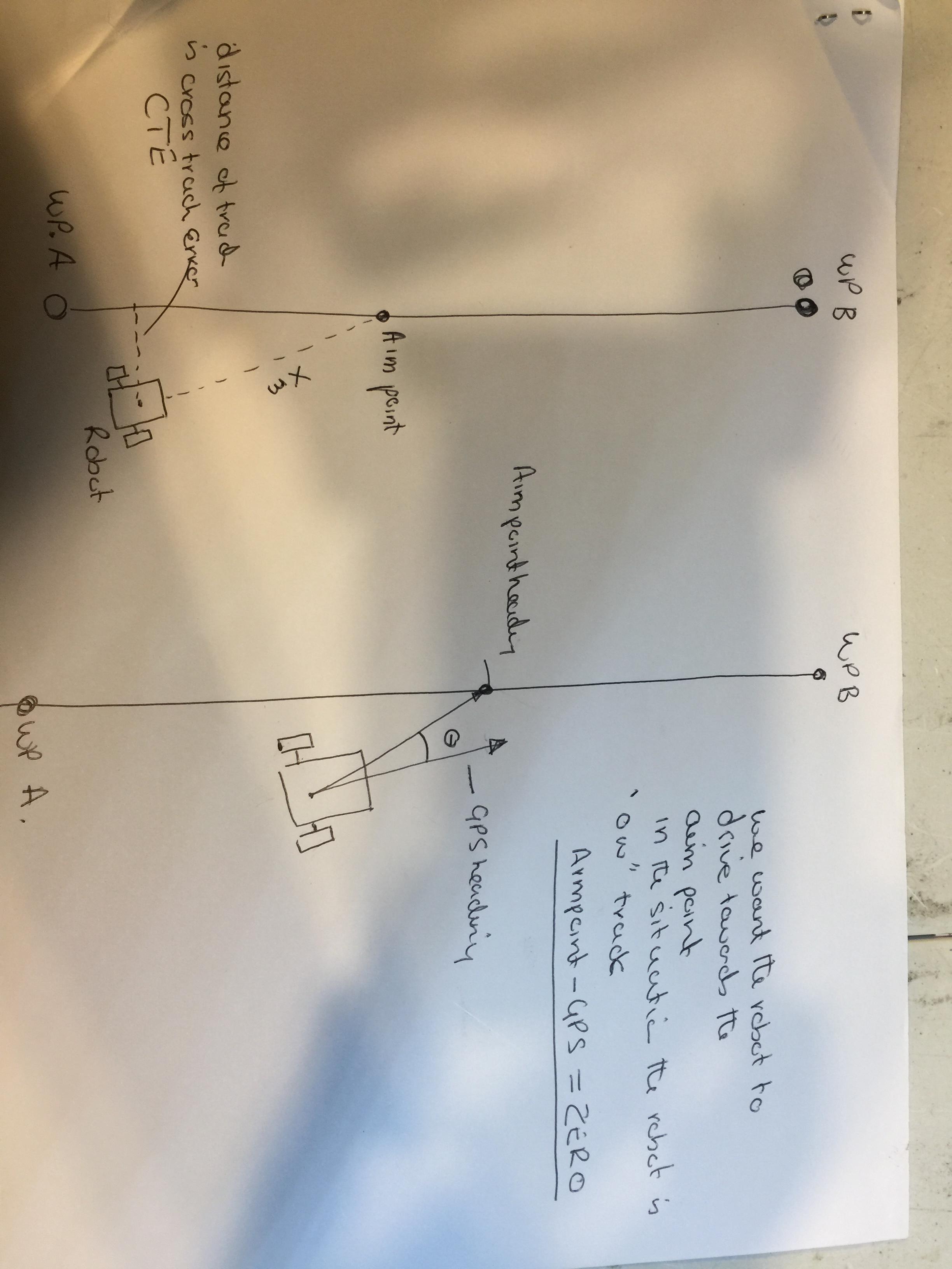
I am also enclosing 2 drawing to explain what we are attempting to do with the pure pursuit PID We first start with 2 waypoints. The robot calculates the heading to a point on the straight line between the 2 way points at is a fixed distance from the robot. As the robot moves the aim point is continuously recalculated.
We then calculate a heading to this aimpoint and from the RTK dual antenna gps we determing an accurate heading of the robot. The difference in the angle between the aimpoint and the gps heading (error) is fed into the PID controller on an Arduino Due.
The output of the controller is a turnSpeed. This turnSpeed is then added to a constant forwardSpeed of 550 to formulate a left and right wheel speed. So if both L and R wheel speeds are 550 the robot drives straight. As the turnspeed increases in one direction so does the differential between the 2 wheels speeds. The wheelspeeds are fed to the Roboteq MDC2230 motor controller with a number from -1000 to +1000 and this generates a voltage to the wheel motors. The application of the differential voltage caused the robot to drive forward and if required drive in a direction to reduce the error between the Aimpoint and GPS to ZERO
So the input to the controller is the difference between aimpoint and gps heading The output of the PID controller is a turnSpeed which is modified to by 2 wheelspeeds.
These wheelspeeds then cause the robot to drive in some direction until the whole system is updated
The loop time for the PID is 5 Hz. We print the data for the excel every second however we can increase that to 5 Hz as well
If you can use the info I have provided to help me select the correct data for your tuning model I would be very grateful.
Also not sure how to do a step impulse for this system. A little clarity on this will also be appreciated.
 August 20, 2020 at 5:32 pm #45Participant
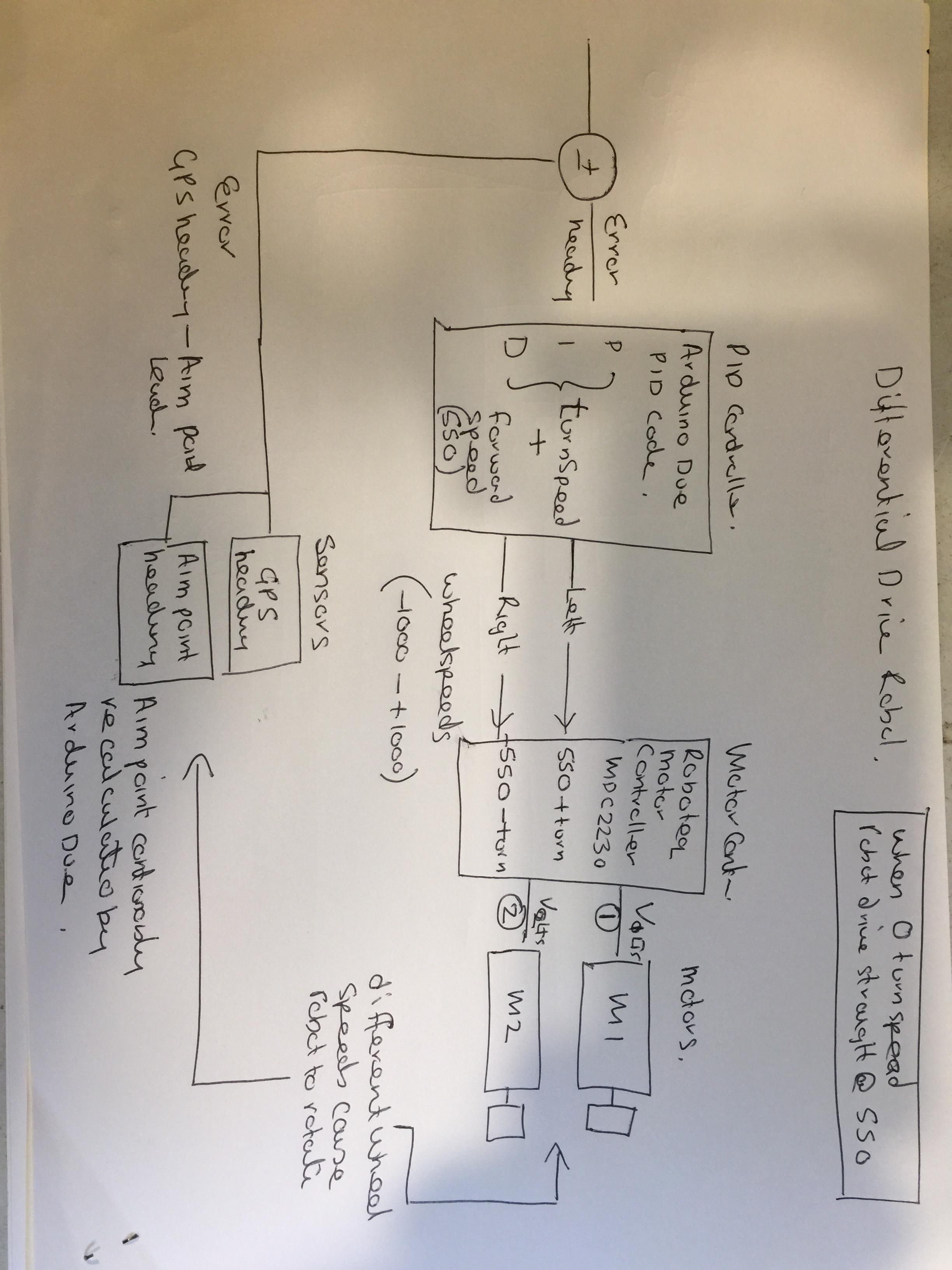
I can also provide our excel file of the data we record
August 20, 2020 at 5:36 pm #46ParticipantAugust 20, 2020 at 8:14 pm #47KeymasterHi,
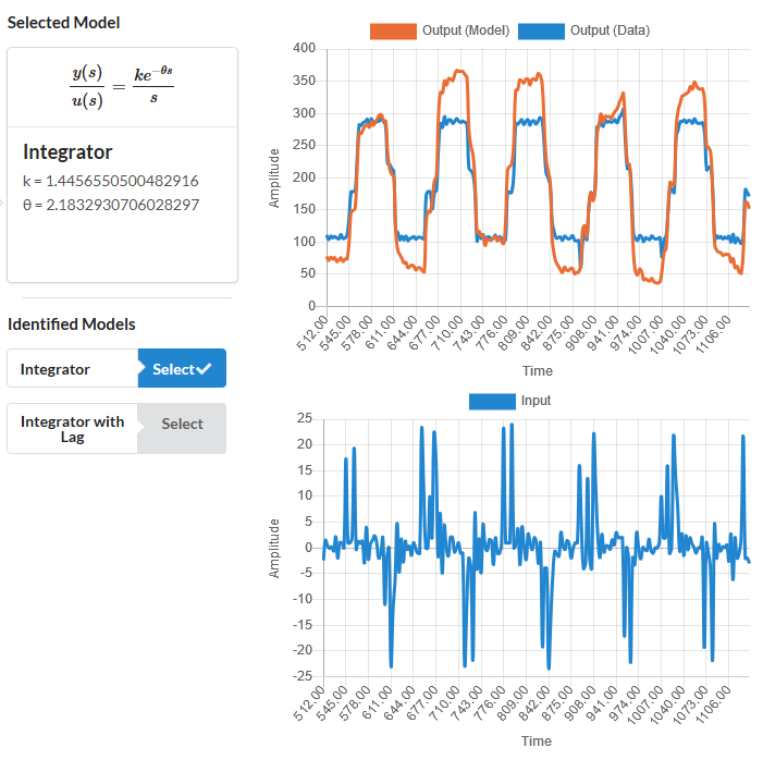
The input to the pidtuner should be the “TurnSpeed” and the output should be the “GPS Heading”. I tried to import your data to the pidtuner using the “Loop Timer” as the time, but divided by 1000 to get the seconds.
Sadly your data does not contain clean manual steps on the input (TurnSpeed). These should be performed in open-loop (PID turned off). Some steps up and down while recording the output (GPD Heading).
Still the pidtuner gave somewhat of a match, see the following link:
https://pidtuner.com/#/0eDJOt49JM
I would try some conservative PID gains first like the ones shown in the link, then if it works, move the slider right to mak the PID gains gradually more agressive.
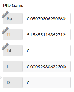
Still the bets thing to do would be to repeat the experiment, providing some clean steps on the “TurnSpeed”.
August 20, 2020 at 9:20 pm #48ParticipantReally appreciate your assistance. Please continue to have patience with me as I am new to all this. I want to continue as I want to learn as much about this as possible
OK The purpose of this robo is to drive a predetermined course. The coirse consists of parallel tracks separated by the width of the robot. The spreadsheet that I enclosed was based on a autonomously operated robot mission driven by a microprocessor. The steering is controlled by a pure persuit PID. The input to the PID is GPS-Aim point heading (or other way round I can not remember) and the output is as you said turnSpeed. The turnspeed is then approtioned to the left and right wheels, If the error between the GPS and AIM point is 0 then turnspeed is 0 and the robot drives straight at the constant forward speed of 550. if the error is plus or minus and is non zero the robot will turn to the left or right as turnSpeed will be also non 0.
The robot is supposed to drive between 2 way points marked as A and B in the drawings. This is the desired track. We measure the cross track error and is is the distance the robot is off the desired track. Currently the cross track error (CTE) is not used in a PID to further reduce the error and to get the robot to better follow the desired track.
I am trying to think of a way to give you useful data manually. Currently the only way to drive between the 2 wp is in auto mode with the microprocessor generating the turn commands.In manual mode the desired track is virtual. I do have a manual mode it is when the robot is controlled by an rc transmitter. In this mode I can drive the robot in any direction and I can make any turn I like. However in this mode we are not generating the aim pint so I can not determine the error (aimpoint -gps heading)
I could lay down some string and manually drive along the string and make manual turns off the desired track and see what is obtained. So help would be needed to further define what is required
I also could set up a long line mission and then in manual drive the robot off the desired track by a fixed amount and then switch to auto so the the robot will try to get back onto the line. I would try point the robot 5 degre then 10 the 20 degrees from where I think the ain point would be,
I am happy to run any experiment that you think will work.
I also do not have a clue regarding what model to choose?
To date I have been using the following gains
D5 is the look ahead distance
purePursuitD5 = 2.0
purePursuitKp = 0.75
purePursuitKi = 0.025
purePursuitKd = 0regards
Max
August 20, 2020 at 9:26 pm #49Participantcurrently the gps is updating at 5hz. So the microprocessor loop time is also 5 hz. If you want me to record the mission data I can do this at 5hz or anything lower like 1 hz
August 20, 2020 at 9:39 pm #50Participantlooking at your site in detail.
The data in the output grapg the data is the gps heading only.
The data in the input graph is turnSpeed.
In our program is is the error between the aim point on the desired track – the gps heading is generating the turnSpeed and not the gps by itself.
In section select a setp. You have selected what we call the pivot this is when the robot to two 90 degree turns with a short 20 inch straight section to move to the next lane.
We are more interested in the longer straight tracks between the pivots, These trcks are about 60 ft long and we want the robot to not wonder off the straight line in between. Currently we can control the robot to be +-5cm from the desired line. We want to see if we can reduce this cross track error CTE even further. Ie that the robot drives even straighter.
In section 3 I have not clue as to which model to select. I normally use Brett Beauregards PID library and we tune for Kp Ki Kd
I am not sure about the other form of the PID equation that uses a general gain and Time constants approach.
August 20, 2020 at 10:26 pm #51ParticipantIn the spreadsheet the GPS heading is in column I
AimPoint is in column O
the error for the PID is either I-o or O-I can not remember I minus will make a turn one way and a + will make a turn the other way
The error will generate a turnspeed as recorded in column U.
This is then apportioned (added and subtracted ) to the left and right wheel speeds ie with a constant forward speed of 550.
the robot drives and then we calculate the error in cross track ie the CTE. This value is not currently feedback as we only use the aimpoint gps error.
Shortly we are going to implement a separate PID to be totally comtrolled by the CTE.
Eventually we may use both PID’s cross track and pure persuit, At the moment we are still learning and a combo could be one step to far
regards
August 21, 2020 at 9:48 am #52KeymasterAssuming you have setup your hardware correctly, the PID controller does not care about the details of all of it. To tune the PID controller, we just need a simplified “model” for everything that is outside of the PID controller. So for a moment, please forget about your hardware details, and think as if you were the PID controller and know nothing about what is outside.
We are the PID controller, and to know what gains to use, we will try to guess what it is that we need to control. So we will try to obtain that simplified “model” of the outside. The input of such “model” is the output of the PID controller, and the output of the “model” is what we feed as input to the PID controller. In your specific case the input of the “model” is the what gets out of the PID controller, so the TurnSpeed. The output of the “model” is what we are trying to regulate or steer, which your case is the GPSHeading.
I understand that you also use a “Setpoint” (what you call “Aim”) to form the error that is then fed to the PID controller, but we will forget about that “Aim” as well because the “Aim” does not get affected by a change of the TurnSpeed, only the GPSHeading is affected by the TurnSpeed, so the “Aim” is like an external disturbance and is not relevant for our model, because we are only interested in what we can actually control.
So we are the PID controller, how to we model everything that is outside us? Well, we do as any person would do. We make experiments and see what happens. Since the TurnSpeed is the only variable we can manipulate, me make a small change to it and see what happens. We go a little bit up and little bit down and we see how the GPSHeading responds, because that is the variable we want to regulate.
Control theory tells us that if we design that experiment to be a step change on the input (TurnSpeed), we get enough information to create a “model” that is good enough for control (good enough to make a good PID controller tuning).
And this is what the pidtuner tool helps you to do. It takes your step response experiment and makes a “model” of everything that is outside of the PID controller, and then uses that “model” to give you some PID gains that will be good enough to regulate that “model”.
So you give your data to the pidtuner in Step 1 of the tool, then on Step 2 you select a time range in your data where you can select where a step change in the input (TurnSpeed) occurs, so when your click next, the pidtuner can generate some models for you.
Notice that I said before; “to regulate that model”, meaning that the “model” has to resemble reality somehow, for the PID tuning to be successful. That is what you see in the Step 3 of the tool where it says “Select Model”. It compares the output generated by the models that the pidtuner has created for you, against the actual data of your experiment. Your job in that step is to select a model that resembles the actual data. The closest the model output looks like the data, the better. It does not has to be perfect though, there is some room for error in the gain, as long as the relevant dynamics are captured.
If no model resembles your data then you have to get back to any of the previous Steps. Either go back to Step 2 and select a different time range that contains better information about the step response. Or even go to Step 1 and import data from a better experiment. This is what I proposed to you, to make a better experiment by making manual steps in the TurnSpeed. If you want to see how a good experiment looks, take a look at the sample data that the pidtuner has by default. That data is actually from a drone pitch angle response.
Once you have a good model-data match, you can get to Step 4 and get the PID gains that you need. In Step 4 you can simulate how the “model” would respond to a change on the “Setpoint” (for you is the “Aim”). You can use the “Scale Gains” slider to make the PID gains more or less aggressive. Then you can see how much time it would take for the model to reach the desired “Setpoint” (“Aim”). Beware that the more aggressive you tune the PID gains, the less robust it will be. That can be seen in the Bode Plot that is shown also in Step 4, but understanding robustness trade-off against performance and how it relates to the Bode Plot is too complicated to explain here and requires university level of engineering studies. You can get a grasp of it by watching some youtube videos though. If you are interested, checkout the youtube channel of Brian Douglas:
https://www.youtube.com/watch?v=ThoA4amCAX4
But you really don’t need all that advanced knowledge just to tune your PID, just follow the instructions I gave you for the tool and you should be good to go.
August 24, 2020 at 10:13 am #53ParticipantWhat a fantastic response. You can alway tell someone that really loves what they do. you are a credit to your interest
I am only delaying my response as I want to digest all that you have said and come back with a worthy response (or not if I finally get it)
once again meeting people like you in hyper space is a real pleasure
Max
-
AuthorPosts
- You must be logged in to reply to this topic.